
 Алгебра
 Английский
 Биология
 География
 Геометрия
 История
 Русский
 Обществознание
 Физика
 Химия
Химия Информатика
 Литература
 Математика
Вопрос:
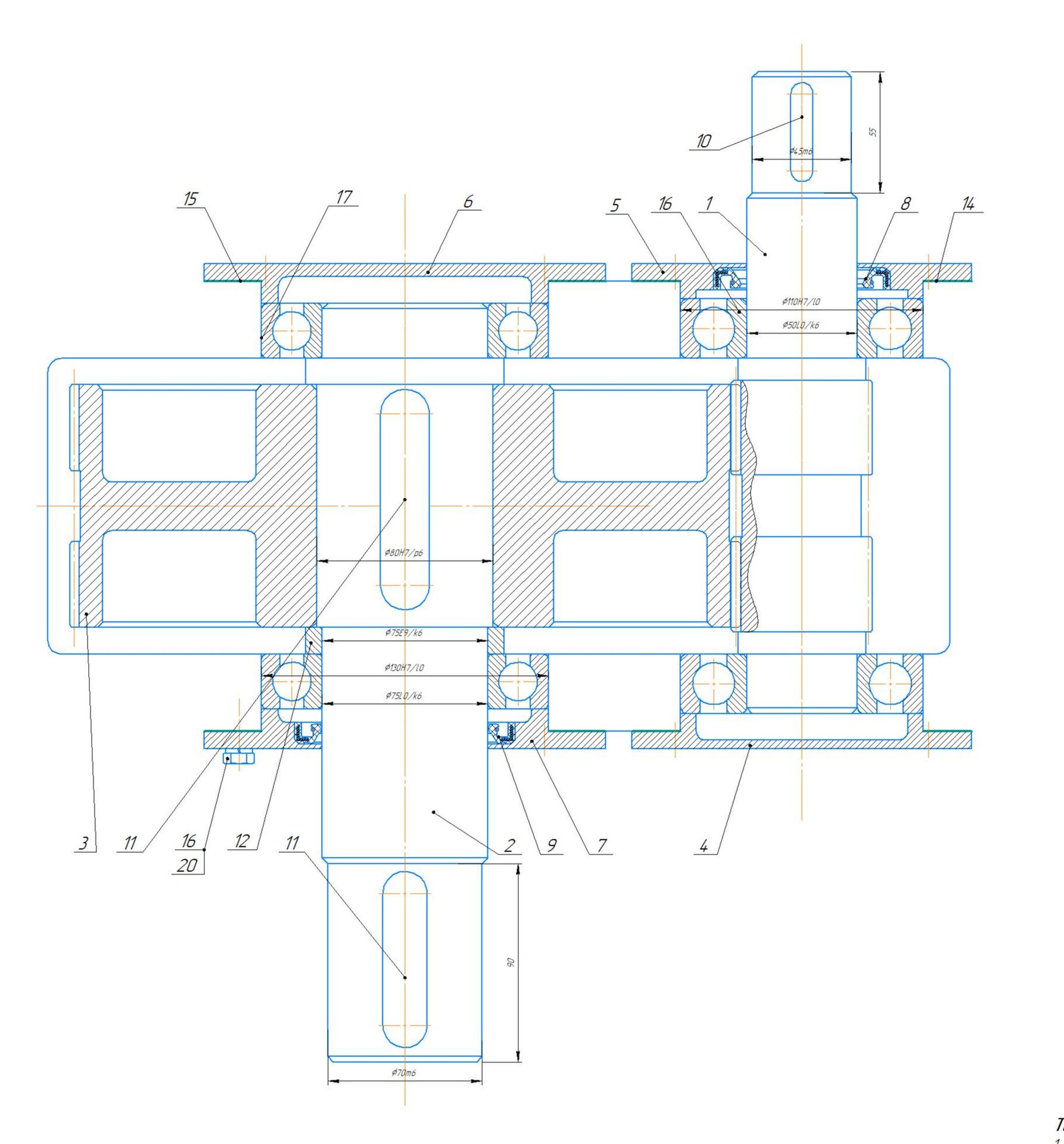
This is an image of a technical drawing with various components labeled with numbers and dimensions. The user wants to analyze the technical drawing data.
Ответ:
Technical Drawing Analysis
The image displays a technical drawing of a mechanical assembly. Key components are identified by numerical labels, and various dimensions and specifications are indicated.
Labeled Components and Dimensions:
- 1: Shaft component with bearing seatings.
- 2: Housing component.
- 3: Bracket or support.
- 4: Base or mounting plate.
- 5: Flange or collar.
- 6: Gear or sprocket.
- 7, 8, 9: Bearing elements.
- 10: Keyway or slot on a shaft.
- 11: Fasteners or pins.
- 12: Seal or retainer.
- 14, 15, 17: Mounting or structural elements.
- 16, 20: Additional components or fasteners.
Key Dimensions and Tolerances indicated:
- Shaft (likely component 1): \( 50L\cdot/k6 \), \( 110H7/10 \).
- Housing/Shaft Bore (likely related to bearings): \( 75L\cdot/k6 \), \( 130H7/10 \), \( 80H7/p6 \).
- Shaft/Pin (likely component 10): \( 4.5m6 \).
- Overall Height/Length: 55, 90, 70m6.
The drawing uses standard engineering line types and symbols to represent the assembly, including section views and dimension lines.
